

『Manual for Metal Rotor Flow Meter』Related information(v cone flow meter|rotary gas meter|gallon meter|gear meter|metal tube rotameter|glass tube rotameter|nutating disk meter|transit time ultrasonic flow meter|wedge flow meter|pd meters|hydraulic flow meter|ultrasonic water flow meter|water flow meter|air flow meter|magnetic water flow meter|oxygen flow meter|gas flow meter|argon flow meter|air velocity meter|gasoline flow meter|fuel flow meter|ultrasonic water meter|digital water meter|nitrogen flow meter|solid flow meter|Oxygen tank flow meter|digital water flow meter|diesel fuel flow meter|steam flow meter|02 flow meter|compressed air flow meter|oil flow meter|liquid flow meter)
1. Main technical parameters of metal rotor flowmeter
(1) Basic measurement range: Water (20 ℃) 2.5-150000L/h Air (20 ℃ key type, 0.1013MPa) 0.07-4000Nm3/h Range ratio: 10:1 Accuracy
1.5/2.5 Working pressure: ≤ 6.4MPa Working temperature: -40~350 ℃ (fluoroplastic lining -10~80 ℃) Environmental temperature: -20~80 ℃ Medium viscosity: DN15 ≤ 5mPa. SDN25~DN150 ≤ 250mPa. S Pipe body material: 1Cr18Ni9Ti, 316L, lined with PTEF, etc. Process connection: flange, or according to the steam provided by the user. Head: flange, DN15/PN1.6, Or as provided by the user
(2) Remote transmission device ① GD 5W1-1 angular displacement transmitter basic error
1.5% F.S output signal: 4-20mA load impedance: 350 Ω power supply voltage: 24VDC ambient temperature: -30~80 ℃ outlet: M20 × 1.5 explosion-proof mark: ExibIICT4 ② GD E-HD transmitter power supply influence:<0.1% (excluding digital resolution [70 μ A]) load influence:<0.1% (excluding digital resolution [70 μ A]) current loss: 4-21.6mA, 0% relative to the measured value load impedance: 0-800 Ω working voltage: 12.8-30VCD two-wire Rext [K Ω]=(Power supply [V] -12.7)/22mA output signal: 4-20mA ambient temperature: -25~80 ℃ outlet: M20 × 1.5 explosion-proof mark: ExibIICT6 measurement range: water (20 ℃) 2.5-150000L/h, air (20 ℃, 0.1013MPa) 0.07-4000Nm3/h range ratio: 10:1 accuracy
1.5/2.5 Working pressure: ≤ 6.4MPa Working temperature: -40~350 ℃ (fluoroplastic lining -10~80 ℃) Environmental temperature: -20~80 ℃ Medium viscosity: DN15 ≤ 5mPa. S, DN25~DN150 ≤ 250mPa. S Pipe body material: 1Cr18Ni9Ti, 316L, lined with PTEF, etc. Process connection: flange, or according to the users preferred steam sleeve: flange, DN15/PN1.6, Or according to the speci
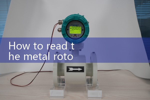
2. How to read a rotor flowmeter? Why?
The reading method for the rotor flowmeter is as follows: For the sub flowmeter reading method, stand in front of the flowmeter, with your eyes parallel to the float, and move your line of sight horizontally to the left until you see the outline of the float touching the positioning line. The corresponding reading value is at the intersection of the positioning line and the horizontal scale in the middle of the float.. A rotor flowmeter measures fluid flow based on the principle of throttling, but it changes the flow area of the fluid to maintain a constant differential pressure between the upper and lower parts of the rotor. Therefore, it is also known as a variable flow area constant diffe
 Hot News
 Related AD